|
Click on the
thumbnail to maximize the image |
The Disc Filters belong to the side feed group and have been around for many years. They are generally used in heavy duty applications such as the dewatering of iron ore taconite, hematite, coal, aluminum hydrate, copper concentrate, pyrite flotation concentrates and other beneficiation processes. The high time for Disc Filters was in the 60's when the metallurgical industries were booming and filters with 300 m2 and larger were manufactured.

|
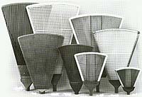
The filter consists of several discs, up to 15 in the larger machines, each made up from sectors which are clamped together to form the disc. The sectors are ribbed towards the neck and designed for a high capacity drainage rate. One of the main features is that the required floor space taken up by disc filters is minimal and the cost per m2 of filtration area is the lowest when compared to other vacuum filters. During operation each sector enters submergence and a cake is formed on the face of the discs. It then emerges to the drying zone, the liquid drains to a central barrel and from there through a valve to the vacuum receiver. The valve with its bridge setting controls the timing so that once the sector leaves the drying zone it moves over a separating bridge and a snap or low pressure blow is applied to discharge the cake. Scraper blades on the side of each disc guide the cake to discharge chutes which are positioned between adjacent discs and are wide enough to avoid their clogging by the falling cake. A paddle type agitator located at the bottom of the tank maintains the slurry in suspension which in most of the metallurgical applications contains solids with high specific gravity which are fast settling and abrasive. |
Move mouse pointer
over the menu to view the components
|
|
The filter consists of the following subassemblies:
Discs and sectors which may be made in injection molded polypropylene, metal or special redwood.
A center barrel supported by the main bearings and consisting of piped or trapezoidal filtrate passages. The sectors are attached to the barrel through "o" ring sealed connections in a number equal to the number of disc sectors.
A valve with bridges and internal compartments for form and dry under vacuum and cake discharge under pressure with 2-2.5 bar snap or 0.2-0.25 bar constant blow. Most disc filters are fitted with one valve only however two valves are often mounted on both drive and non-drive ends with long barreled filters or when the hydraulic loadings are high.
An agitator with paddles that are positioned between the discs and far enough not to interfere with the forming cake.
A tank which, on its discharge side, has separated slurry compartments for the discs and discharge chutes for the blown-off cake. When the solids are of an abrasive nature it is advisable to line the bottom portion of the tank that cradles the agitator with rubber.
Two cake discharge blades on both sides of each disc are suspended from a frame mounted on the tank and serve to deflect and guide the cake to the discharge chutes. On large diameter filters the blades are of the swing type that float to maintain the cake to disc clearance and so allow for the wobble of the turning discs.
An overflow trough that spans across the entire tank length and ensures full submergence of the sectors in the cake formation zone since an exposed sector in the 6 o'clock position will cause immediate loss of vacuum.
The main considerations in selecting a Disc Filter are:
The operation sequence of a Disc Filter is, except for washing, similar to a Drum Filter.
Let us follow a sector as it passes from zone to zone:
Disc Filters are subjected to high wear due to the presence of abrasive solids in the various process slurries. Attention should be given to the following subassemblies:
The agitator, its bearings and stuffing boxes.
The wear plate that is mounted on the barrel and seals against the valve face.
The cloths or mesh screens that cover the sectors since they are susceptible to wear and tear.
The clamps which join the sectors at their periphery to form the disc. These clamps, being part of the disc, move at a high peripheral speed and pass near the agitator so if they wear out the sectors may fall apart.
The tips of the cake deflecting blades on both sides of each disc. Likewise, the suspension that enables the swinging of the blades should move freely and follow the wobble of the disc.
The tank should be inspected during shut-downs for erosion and with special attention to the agitator's cradle.