| Click
on the thumbnail to maximize the image |
Description
The Rotary Vacuum Drum Filter belongs to the bottom feed group and is one of the oldest filters applied to the chemical process industry.
The filter consists of the following subassemblies:
|
|
|
|
The majority of drum filters have a valve with three bridge blocks and a single row pipe plate as shown below and on the right. The duty of the bridges is: (please also refer to Operational Sequence)
Vacuum and blow zones separating bridge. This bridge cuts off the vacuum so it is slightly wider than the internal pipe port.
Dead zone bridge. This bridge opens to vacuum once a compartment submerges.
Start-up assist bridge. At start-up the upper vacuum zone is open to atmosphere and a cake may be formed only when closing the valve that controls this zone. Once the cake starts to emerge from the tank the valve is gradually opened and fully opened when the entire drum face is wrapped with the cake. Since in continuous operation both lower and upper zones are under vacuum this bridge is slightly narrower than the internal pipe port so that the vacuum is continuous and the cake is held onto the drum.
However, there are also more complex drum filters such as lube oil dewaxers. These filters have a sophisticated valve that allows very quick evacuation of residual wash liquid from the descending compartments by purging inert gas through the internal piping manifold prior to cake discharge. The images below show the two different valves with their single and double row pipe plates:
The exploded view below shows the assembly components of a typical "one row" set-up:
|
To view the components
move mouse pointer over the menu
 |
The internal piping manifold and the various leads and trail options discussed above are shown here:
|
|
The clip below shows the internal drum piping of the "two row" manifold. The trail pipes shown in red are normally handling the mother filtrate on the ascending side of the drum up to the 12 o�clock position and then the lead pipes shown in blue handle the wash filtrate on the descending side. The trail pipes are always connected to the outer row and have a bigger diameter than the lead pipes that are connected to the inner row. The reason for this arrangement is that the trail pipes handle more liquid than the lead pipes so require a bigger cross section to avoid vacuum losses.
 |
|
|
|
|
|
|
The Cake Discharge Mechanism
Click on the thumbnails to maximize images
The cake discharge mechanism that can be either a scraper, belt, roll and in very rare cases a string discharge. Blow is applied only to filters with scraper and roll discharge mechanisms but not to filters with a belt or string discharge.
The images on the left illustrate the various mechanisms.
The selection of a suitable type of mechanism depends largely on the release characteristics of the cake from the filter media and will vary from process to process. Scraper discharge mechanisms will suit cakes that release readily and roller discharge mechanism are better for thixotropic cakes.
The Drum Speed Variation
The drum filter has a drive with a variable speed that rotates the drum at cycle times that normally range from 1 to 10 MPR.
The Agitator
An agitator keeps gently the slurry in suspension and reciprocates between the drum face and tank bottom at 16 or so CPM.
The clip below shows a typical agitator:
The Tank
The tank that houses the drum and agitator has baffled slurry feed connections, an adjustable overflow box to set a desired drum submergence and a drain connection. The tanks are normally designed for an "apparent submergence" of 33-35% however on certain applications 50% and more is possible. With these special designs the tank ends are higher in order to accommodate stuffing boxes on both the drive shaft and valve end trunnion.
The Cake Washing Manifold
On applications where cake washing is required, 2 or 3 manifolds with overlapping nozzles are mounted to a pair of splash guards bolted to the tank ends. The position of the manifolds and the quantity of wash liquid are adjustable depending on the wash characteristics of the cake.
Control Instrumentation
Optional controls may be used to automate settings such as drum speed, applied wash liquid and drum submergence for a desired cake thickness or throughput. The monitoring of drum submergence controls the slurry feed valves so an adjustable overflow weir is not necessary except for a fixed connection in case of emergency.
The flow scheme of a Rotary Drum Filter Station will generally look like this:
Operational Sequence
The entire filtration cycle on a rotary drum filter must be completed within a geometry of 360 degrees. Let us follow the cycle sequence of a single sector assuming that the drum rotates in a clockwise direction while viewing the valve end:
Cake Formation Zone
Cake Predrying Zone
Cake Washing Zone
Cake Final Drying Zone
Cake Discharge Zone
Dead Zone
All Zones
To view the zones move the
mouse pointer over the menu
![]()
Cake Formation
With the overflow weir set to a maximum the "apparent submergence" is normally 33-35% so the slurry levels between 0400 and 0800 hrs. Once a sector enters submergence vacuum is applied and a cake starts to form up to a point where the sector emerges from the slurry. The portion of the cycle available for formation is the "effective submergence" and its duration depends on the number of sectors, the slurry level in the tank and the bridge setting which controls the form to dry ratio.
Cake Washing and Drying
After emerging from submergence the drying portion of the cycle commences and for non-wash applications continues to about 0130 hrs where the vacuum is cut-off. If cake washing is required the wash manifolds will be located from about 1030 to 1130 hrs and the remaining time to vacuum cut-off at 0130 is the portion allocated to final cake drying.
Cake Discharge
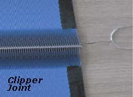
After vacuum for the entire sector is cut-off air blow commences at about 0200 hrs in order to facilitate cake discharge. The blow, depending on the position of the tip of the scraper blade, will cut-off at approximately 0300 hrs. Drum filters are normally operated with a low pressure blow but on certain applications a snap blow is applied and to avoid the snapping out of the caulking bars or ropes wire winding of the cloth is recommended . Blow is used on scraper and roll discharge mechanisms but on belt discharge filters vacuum cuts-off when the filter media leaves the drum.
Dead Zone
Once the blow is cut-off the sector passes through a zone blocked with bridges so that no air is drawn through the exposed filter media which might cause the loss of vacuum on the entire drum surface.
Selection Criteria
In broad terms drum filters are suitable to the following process requirements:
- Slurries with solids that do not tend to settle rapidly and will remain in a uniform suspension under gentle agitation.
- Cakes when a single washing stage is sufficient to remove residual contaminants from the cake or yield maximum recovery of filtrate.
- Cakes which do not require long drying times to reach asymptotic moisture values.
- Filtrates that generally do not require a sharp separation between the mother and wash filtrates. Some complex valves, however, enable atmospheric purging of the sectors and internal piping to facilitate a sharp separation of filtrates.
- Filtrates that are acceptable with a low quantity of fines that pass trough the filter cloth in the first few seconds of cake formation. Broadly, and depending on particle size and cloth permeability, the filtrate may contain 1000 to 5000 ppm insolubles.
- For very corrosive applications plastic drum filters are available with up to 10-15 m2 filtration area.
Maintenance
The slow rotation of the drum and reciprocation of the agitator reduce maintenance requirements to a minimum but the following should be inspected periodically:
The strip liner of the trunnion bearing at the valve end will normally wear at the lower half. However, in cases when the slurry has a high specific gravity, the drum may become buoyant causing a wear to the upper half. At this point it should be mentioned that one way to remove the lower half of the liner, when hoisting facilities are not available or operational, is to float the drum by filling the tank with a sufficiently concentrated solution.
The stuffing boxes on high submergence filters should be inspected for leakage and, if necessary, the stud nuts should be tightened. It should be noted that excess tightening can increase substantially the load on the drum drive so the use of a torque wrench is recommended.
The face of the wear plate should be checked periodically and remachined if necessary. A whistling noise during operation is an indication the wear plate is worn out or the valve spring requires tensioning.
The drum has a bailer tube that protrudes from the drive end shaft and must be kept open to atmosphere at all times since its blockage may cause the collapse of the drum. The bailer tube is a tell-tale indication to the following:
If a lighter flame is drawn through the bailer tube to the inside of the drum it indicates that a vacuum leak exists in the drum shell or the internal piping. It should be noted that in certain instances there is a possibility that explosive gases build-up inside the drum and may pose a safety hazard. In such cases the use of aerosol type smokes or a light tissue paper should be used instead of an open flame to identify a vacuum leak.
If liquid leakage is observed from the bailer tube it indicates that a hole exists in the drum head causing penetration of slurry from the tank into the drum.
The on-line filter on the wash headers manifold should be checked periodically for pressure build-up due to progressive blockage. Likewise, the nozzles on the wash headers should be kept clean in order to ensure overlapping for full coverage of the washed cake.