| Click on the thumbnail to maximize the image |
Description
The High-Rate thickeners became popular in the mid 1980's and are relatively newcomers to the sedimentation line of equipment. As already discussed previously Thickeners are a major component in a plant layout and occupy large spaces which may be saved by introducing high-rate machines. Furthermore, they are normally positioned far away from the center of the plant so to allow gravity feed and thus save pumping costs their distance is influenced by the hydraulic gradient for the large flows. This factor determines the elevation of the entire plant and consequently has a substantial impact on capital investment.
Among other advantages is the smaller volume of the tank so it speeds up startups or shutdowns and less volume is required for storing the product in the event that the tank has to be emptied. Likewise, high-rate thickeners consume substantially less flocculants with savings up to 60%.
There are operations where the process requires a constant temperature control or eventually indoors installation so the saving in the cost of insulation and roofing of conventional thickener tanks may prove to be another feasible solution in selecting a high rate thickener.
The concept of speeding-up settling rates to reduce the size of conventional thickeners is closely associated with an improvement in the efficiency of flocculating agents. Therefore, high-rate thickening is mostly applied to tails and slimes but not so often to metallurgical concentrates such as iron ore where the settling rates are very high and the underflow reaches its ultimate density almost instantaneously.
In fact, the entire concept depends on two major factors:
There are also other factors to consider:
That the floc is sufficiently stable or exhibits good self-reforming properties so that it will not disintegrate inside the thickener tank.
That the flocculant solution will be prepared in a mixing ratio that will intimately bring in contact the small solution volume with the large flow of the incoming stream.
That the dosage of polymer will be properly controlled by the incoming feed so that an overdose will not cause floc disintegration something that happens in many instances.
That the feed launder or pipe will run straight or with long radius elbows that will not break the fragile floc.
That the feedwell will reduce sufficiently the incoming stream velocity.
That the raking arms will not cause "doughnutting" of the settled solids while being conveyed towards the discharge cone.
That the storage of underflow is not required since not all high-rate thickeners are designed to accommodate a raking arms lifting device.
That the liquid reporting to overflow and its passage over the weir is quiescent and evenly distributed.
That the mass balance of underflow pumping and rake arms conveyance will not cause a "rat hole" in the discharge cone or conversely a sludge pile-up.
That the density of the underflow will be as high as possible to reduce the load on the disposal facilities or, if further processed, reduce the size of downstream equipment such as filters or centrifuges.
In most cases, if these requirements are met and proper test work is done, high-rate thickeners may replace conventional thickeners and depending on the application they are capable of delivering a throughput that is 5-10 higher than with a conventional machine of equal size. This prompted a tendency to retrofit existing installations at a substantial saving in capital investment when increased capacity was required.
|
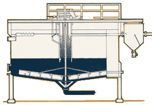
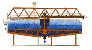
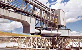
High-rate thickeners that are built as dedicated machines are available in sizes up to 40 meter diameter but retrofits of conventional thickeners are often larger in size. When viewed from the outside high-rate thickeners look very much like conventional machines except that their tanks have a greater height to diameter ratio. Their height is derived from test work by calculating retention time and the reduced area as obtained for the increased throughput. |
Another difference that may be seen externally is the absence of lifting devices since there are designs with internals that do not leave sufficient clearance for the lifting of the arm truss.
|
As to the internals, there are several approaches to the mechanism of hi-rate thickening. There are design options such as deep feedwells with progressive flocculation along the incoming stream route, direct injection into the feedwell or recirculation of liquid from the clear zone to enhance settling rate by diluting the feed internally. There are also concepts that resemble sludge-blanket clarifiers with feedwells that are submerged in the sludge bed and provide an additional benefit of trapping the fines to produce a clear effluent.
|
High-rate thickeners are suitable for processes such as:
The Thickener Components
As mentioned previously most of the high-rate thickeners subassemblies are similar to those of conventional thickeners except for lifting devices that are not available on all units due to design restrictions. The similar components may be seen in the following links:
The Feedwell
The basic feedwell design has not changed for many years and the concept was traditionally just to introduce the feed tangentially, let it swirl as it moves down the feedwell, then divert it horizontally and spread it evenly below the surface of the clarified liquid zone in the tank. It is very common to use a slurry velocity of about 2 m/s to maintain the solid particles in suspension as they flow through pipes and launders so these measures are necessary in order to avoid internal currents that may otherwise interfere with the slow settling rate of the solids.
The conventional feedwell consisted of a smooth cylinder with no internals but in the early 60's, on a red mud application in an alumina plant in Jamaica, a shelf was introduced at the bottom of the feedwell to improve flocculation. This, named the Jamaican Feedwell, was the first approach to modernizing and creating more favorable conditions for the flocculation process and polymer consumption.
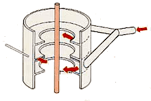
The new generation of feedwells is designed to improve the mixing efficiency between the small volume of flocculant solution and the high volume of the main stream by diluting the stock solution and introducing it at a point with maximum shear that will not break the build-up of the gentle floc.
A unique design that meets these requirements may be seen in the picture below:
|
The high velocity feed is split to two compartments with opposite tangential inlets that are positioned in two levels, an upper and a lower one. Between those compartments there is a narrow gap through which the flocculant solution is introduced and the high shear quickly distributes the polymer to a uniform mixture. Simultaneously, the shearing planes dampen the flow velocity to a point where the floc may grow without being interrupted by irregular flow patterns. |
The Feed Pipe
Thickeners are almost always operating on slurries in the 3rd category of mass subsidence and hindered settling so high feed solids concentration yields slow settling rates and vice versa. On the other hand slurries in the 1st category of free and unhindered settling exhibit high settling rates of the solids in the suspension. This concept of diluting the incoming slurry feed with clear liquid was adapted in the past on several installations but it had a basic drawback since the additional recirculated liquid increased overflow rate and caused fines to report to the overflow.
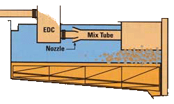
An interesting design was developed in the early 90's that uses a ventury nozzle to draw liquid from the clear zone and dilute the incoming feed internally without effecting the overflow rate. The principle is shown in the picture to the left:
In this design a special compartment dissipates the energy of the incoming feed and its outlet is directed towards the nozzle and from there on to the feedwell after introducing the polymer solution. The design lends itself easily for retrofits of existing thickeners without being committed to major changes except for raising the feed connection to the compartment so that sufficient head is created as required for the nozzle. When this modification is done the new slope of the feed pipe or launder between upstream equipment and the thickener is shallower so it is necessary to check if this milder gradient is sufficient to maintain slurry velocity to keep the solids in suspension.